(3) Terms related to life
Mechanical life: refers to the life of a switch when the contacts are not energized and the overtravel (OT) is set to the specified value at a specified operating frequency.
Electrical life: refers to the life of a switch when the rated load is connected to the contacts and the overtravel (OT) is set to the specified value at a specified operating frequency.
(4) Standard test conditions
The test conditions for switches are as follows.
Ambient temperature: 20±2℃, relative humidity: 65±5%RH, air pressure: 101.3kPa
(5) The N level reference value
indicates the failure level at a reliability of 60% (λ60).
λ60=0.5×10⁻⁶/times means that the failure rate is less than times at a reliability of 60%.
(6) Shape and type of contacts
(7) Contact spacing
The contact spacing is specified in four types: 0.25mm, 0.5mm, 1.0mm, and 1.8mm. The contact spacing is a design target. If the minimum contact spacing is required during use, please confirm and select. The standard contact spacing is generally 0.5mm. For the same switch mechanism, the smaller the contact spacing, the smaller the MD, the higher the sensitivity, and the longer the mechanical life (lifespan), but it is disadvantageous in terms of DC circuit breaking performance and vibration and impact resistance. Since the current switching of micro switches will cause contact loss, the contact spacing becomes larger, and the sensitivity decreases as the MD increases. Therefore, in order to achieve high sensitivity, when using a micro switch with a contact spacing of 0.25mm, it is necessary to maintain a small switching current to reduce the contact loss caused by current switching. Products with a large contact spacing have good vibration resistance, impact resistance and circuit breaking performance.
For MD (hysteresis distance), please refer to (10) Action Characteristics Terminology (page 745).
|
shape |
name |
Main materials used |
processing method |
The main purpose |
|
|
|
|
|
This is used to obtain stable contact reliability in the micro-load area. |
|
|
Crossbar |
Gold Alloy Silver Alloy |
Welding |
|
|
|
Needle |
silver |
It is used to improve contact reliability in the load range of relay load. |
|
|
|
rivet |
Silver plated silver silver alloy gold plated |
It is widely used in the range from general load to high load. |
(7) Contact spacing
The contact spacing is specified in four types: 0.25mm, 0.5mm, 1.0mm, and 1.8mm. The contact spacing is the target during design. If the minimum contact spacing is required during use, please confirm and
select. The general standard for contact spacing is 0.5mm. For the same switch mechanism, the smaller the contact spacing, the smaller the MD, the higher the sensitivity, and
the longer the mechanical life (lifespan), but it is disadvantageous in terms of DC breaking performance and vibration and impact resistance. Since the current switching of the micro switch will cause the contact to wear out, the contact spacing becomes larger, and the MD
increases, the sensitivity decreases. Therefore, in order to achieve high sensitivity, when using a micro switch with a contact spacing of 0.25mm, it is necessary to maintain a small switching current to reduce the
contact loss caused by the current switching. Products with a large contact spacing have good vibration resistance, impact resistance and breaking performance.
|
Representing characters |
Contact spacing |
DC current cut-off |
Force and travel |
Accuracy and life (lifespan) |
Anti-vibration and shock |
The main advantage |
|
H |
0.25mm |
△ |
Very small |
☆ |
△ |
High precision and long life |
|
G |
0.50mm |
○ |
Small |
◎ |
○ |
General use |
|
F |
1.00mm |
◎ |
middle |
○ |
◎ |
Intermediate characteristics between G and E |
|
E |
1.80mm |
☆ |
big |
△ |
☆ |
Good vibration and impact resistance |
|
☆ : Excellent |
◎ :Good |
○ :Normal |
△ : Bad |
(8) Snap-action mechanism
A snap-action mechanism allows the movable contact to move quickly from one fixed contact to another fixed contact, while being as unaffected by the operating speed as possible. For example, even in the case of a knife switch, if the handle is operated quickly, the movement will become faster. However, this mechanism in which the speed of the operating handle is related to the speed of the contact movement is not called a snap-action type, but a slow-action type. The faster the contact switching speed, the shorter the duration of the arc between the contacts.
This results in less wear and tear on the contacts and allows stable characteristics to be maintained. However, in addition to the speed limit (economic speed) that effectively reduces the amount of arcing, there are also limits due to mechanical problems. In particular, if the switching speed is too fast when closing the circuit, the impact energy between the movable contact and the fixed contact will increase, and the jumping phenomenon (vibration or friction closing) caused by the impact will generate an arc, which will seriously wear out the contacts and sometimes fail to open the circuit, causing the contacts to melt. Mechanisms that perform this kind of quick action generally use spring mechanisms with dead points (critical action points when changing from one state to another state in a jumpy manner).
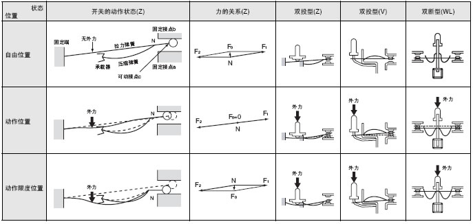
The figure below shows an example of a snap-action mechanism for a micro switch formed by combining a tension spring and a compression spring.
The following is an explanation of the operating principle of a double-throw type (Z) snap-action mechanism.
The figure below shows the relationship of the forces of the switch. In the free position where no external force is applied to the actuator, the reaction force F1 of the compression spring is in a state of equilibrium due to the influence of two forces - F2 and F0. F0 is the pressure that pushes the movable contact c to the fixed contact b.
Next, the actuator applies force to a part of the tension spring to displace the tension spring. At this time, the forces F1 and F2 at point N will increase in sequence, and the angle will approach 180°. Soon, only F1 and F2 will be in a state of equilibrium, that is, F0 = 0. There is
a sliding which will cause the contact to move horizontally and further bend the compression spring. From the position of F0=0, by further applying external force to slightly displace the tension spring, a force in the opposite direction -F0 will be generated, and the movable contact c will be
pressed out from the bottom with the maximum force of the bending compression spring, and the movable contact c will move through the space to the fixed contact a on the opposite side.
Using this operating principle, the microswitch switches the contacts at the inherent switching speed (disengagement speed) of the switch, regardless of the speed at which the external force is generated when the tension spring is pressed. The position when F0=0 is called the operating position, which is
basically .
When the external force is eliminated and the reset operation is performed, it is also based on the same principle, and the bending reaction force of the spring at this time is the reset motive force.
Schematic diagram of the microswitch based on the combination of tension spring and compression spring
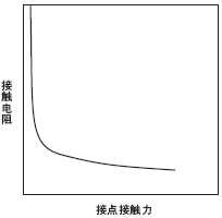
(9) Contact resistance·Contact contact force characteristics
The contact resistance changes according to the contact force of the contact, and the following figure shows the relationship. When the contact force of the contact increases, the contact resistance becomes more stable (decreases), and conversely, when the contact force decreases, it begins to become unstable (increases).
Contact resistance·Contact contact force characteristics
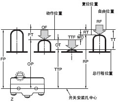
(10) Terms related to action characteristics
|
Definition of action characteristics |
Classification |
term |
Abbreviation |
unit |
Deviation |
definition |
|
|
force |
Operating |
OF |
N |
maximum |
The force that must be applied to the drive rod to move from the free position to the actuated position. |
|
|
RF |
N |
Minimum |
The force that must be applied to the drive rod to travel from the total stroke position to the reset position |
||
|
Total travel |
TTF |
N |
|
The force that must be applied to the drive rod to travel from the free position to the total travel position |
||
|
journey |
|
PT |
mm, |
maximum |
The distance or angle of movement from the free position of the drive rod to the actuated position |
|
|
|
OT |
mm, |
Minimum |
The travel distance or angle from the actuation position of the drive rod to the total travel position |
||
|
|
MD |
mm, |
maximum |
The moving distance or moving angle from the actuating position of the drive rod to the reset position |
||
|
|
TT |
mm, |
|
The distance or angle of travel from the free position of the drive rod to the total travel position. |
||
|
Location |
Free |
FP |
mm, |
maximum |
The position of the drive rod when no external force is applied |
|
|
Operating |
OP |
mm, |
± |
The position of the driving rod when the driving rod is subjected to external force and the moving contact just starts to reverse from the free position state |
||
|
Releasing |
RP |
mm, |
|
The position of the driving rod when the external force on the driving rod is reduced and the movable contact just starts to return to the free position from the actuated position. |
||
|
Total travel |
TTP |
mm, |
|
The position of the drive rod when it reaches the transmission stop position. |
Explanation of deviation
(Example) Z-15G-B OF (operating force) 2.45~3.43N
Explanation: This means that the force applied to the driving rod is increased from 0 to 3.43N, and all switches should operate. For the setting of the switch stroke, please refer to "① About the operating stroke setting" on page 750.
(11) Force, stroke, and contact force characteristics The operating characteristics of a micro switch are expressed as force and stroke characteristics. The following figure shows this characteristic. That is, the horizontal axis stroke (actuator stroke) is applied to the vertical axis actuator, and the force applied at this time is obtained. The characteristics of a micro switch are as follows:
① When operating and returning, the force changes rapidly, and the switching sound of the switch is emitted at the same time, which can determine the operating position (OP) and reset position (RP) of the switch.
② Since there is a response difference stroke (MD), even if the operating body of the actuator moves or shakes up and down, one of the fixed contacts in the movable contact is stable, so the movable contact is suitable for mechanical detection switches.
③Since the switching of the contacts is fast, a large current can be switched in a small switch with a short arc connection time when switching current.
The following figure shows the relationship between stroke and contact force. In the free state, as the actuator is gradually pushed in, the contact force will gradually decrease, and when it reaches OP, the contact force will become zero, and the movable contact will reverse from normally closed (NC) to normally open (NO), and contact force will be generated. If the actuator is pushed in again, the contact force on the NO side will increase. When the actuator is reset, the NO side becomes zero, and then contact force will be generated on the NC side.

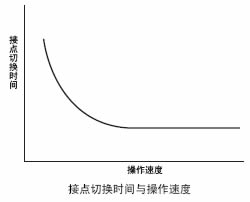
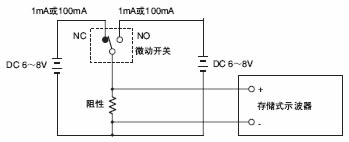
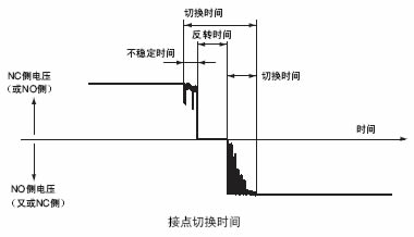
(12) Contact switching time The relationship between operating speed and contact switching time is shown in the figure on the right. As the operating speed of the actuator gradually slows down, the contact switching time will gradually increase. Therefore, the contact switching time is measured at the specified minimum operating speed. The measurement current in the figure below is specified as follows: the current for the micro switch for micro load is 1mA, and the current for the general purpose micro switch is 100mA. As shown in the figure below, the contact switching time is the sum of the unstable time, reversal time and vibration time. The contact switching time of a general micro switch is 5 to 15msec. Here, the unstable time is caused by the unstable contact resistance, and the unstable contact resistance is caused by the reduction of the contact force before the contact reversal and the friction closure of the contact. The
mechanical reversal of the snap-action mechanism will produce the reversal time. The vibration when the movable contact impacts the fixed contact will produce the vibration time. The unstable time and vibration time will cause the contact to heat up and cause the contact to melt. After connecting to the electronic circuit, it may also cause the electronic circuit to malfunction. Therefore, when designing a micro switch, the unstable time and vibration time should be shortened as much as possible.
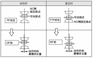
(13) Frictional closure of contacts
Depending on the type of snap-action mechanism, some micro switches have almost no frictional closure (sliding) at the contacts. Frictional closure refers to the action of the movable contact sliding on the fixed contact surface under a certain contact force. The following figure shows the frictional closure of the movable contact when it is in motion and when it is reset. Frictional closure has two effects, namely, the cleaning effect on the contact surface and the tripping effect when the contact melts due to impact current, etc.
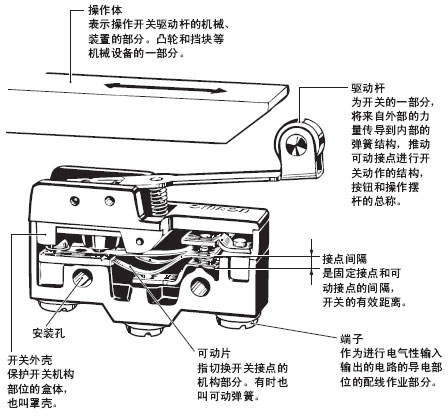
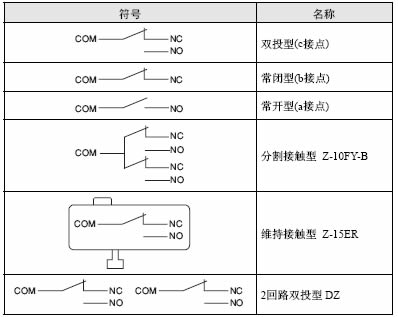
(14) Terminal symbols and contact shapes
|
symbol |
Terminal Symbols |
|
COM |
Common terminal |
|
NC |
Normally closed terminal |
|
NO |
Normally open terminal |
(15) Terminal types
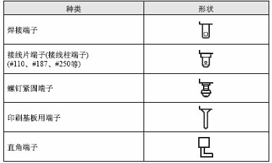
Note: There are also products with lead wires and one-touch connector compatible products whose terminal connection parts are sealed with plastic.
(16) Contact types
|
PTI |
Classification based on UL Yellow Book |
|
500 |
PLC level 1 400≤CTI<600 (the material manufacturer must be confirmed to have CTI500 certification) |
|
|